Meaning of the Reference Edge in Two-Dimensional Inclination Measurement
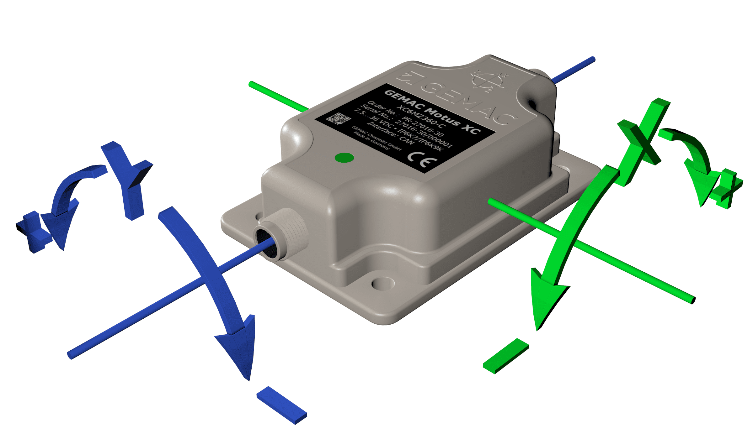
Every sensor from GEMAC Chemnitz is factory-calibrated, including the determination of the axis orientation within the sensor (Figure 1).
Figure 1: Sensor axes using the example of GEMAC Motus®
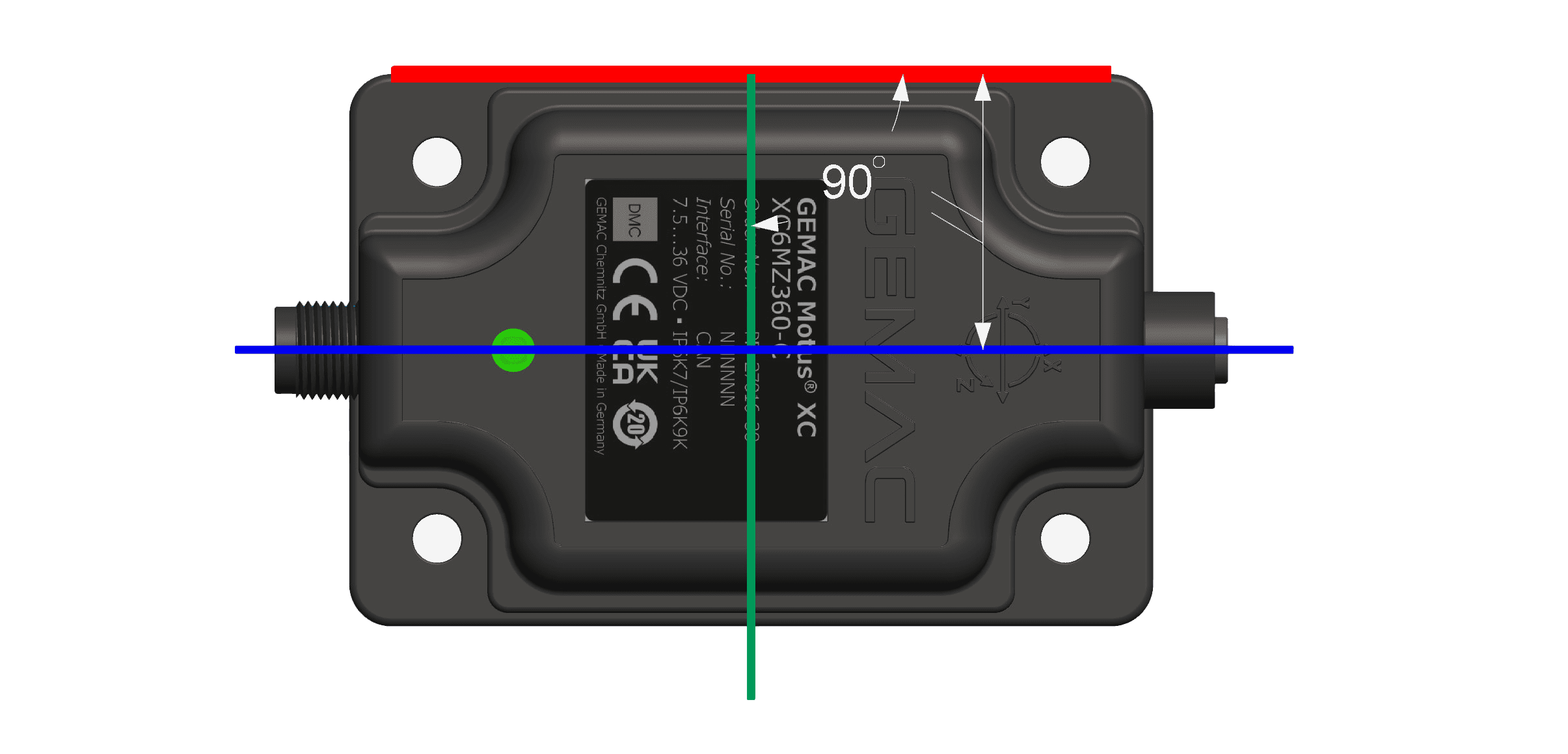
Each sensor has a reference edge for mounting. One axis is aligned parallel to this outer edge, while the other is oriented orthogonally to it (Figure 2).
Figure 2: Axis positions relative to the reference edge
In the application, it is important to ensure that the inclination being measured corresponds precisely to these measurement axes. GEMAC Chemnitz recommends using the reference edge in the application. Any rotation around the Z-axis will introduce measurement errors.
The problem becomes most apparent when there is a 90° rotation. If the inclination along the X-axis is intended to be measured, the sensor will display the inclination along the Y-axis, and the other way around.
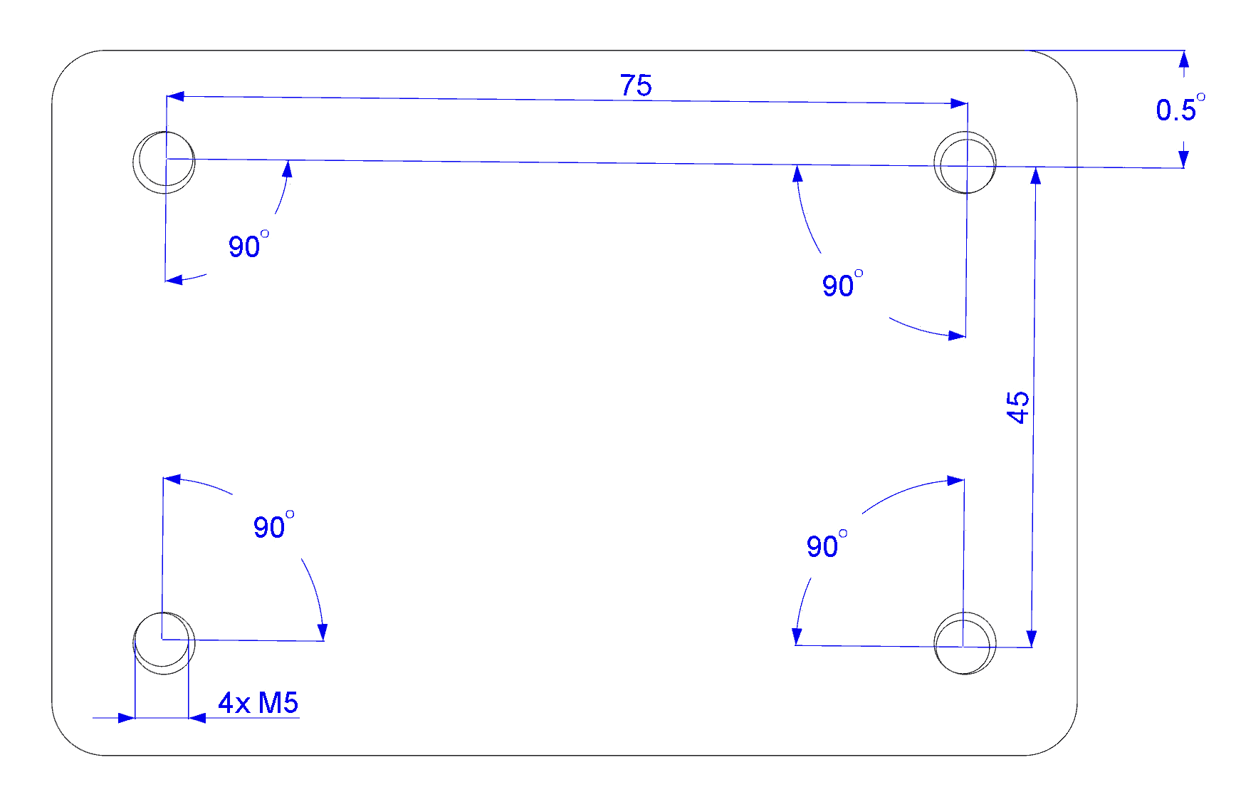
In the following example, a GEMAC Motus® sensor is intended to measure an inclination. The direction of the inclination axis to be measured is not defined by the reference edge but by four precisely aligned mounting points. The mounting holes of the sensor have a diameter of 5.8 mm. According to the user manual, the sensor should be fastened using M5 screws. This theoretically allows for a potential misalignment of 0.5° (Figure 3). If the mounting points are not precisely aligned with the desired measuring direction, additional errors are introduced.
In this example, only the X-axis is being inclined, while the Y-axis remains at 0°. The following tables demonstrate that the misalignment primarily affects the readings of the untilted Y-axis.
| Desired angle X-axis [°] | 0,00 | 1,00 | 5,00 | 10,00 | 30,00 | 45,00 | 60,00 | 80,00 | 90,00 |
| Display angle of X-axis [°] | 0,00 | 1,00 | 5,00 | 10,00 | 30,00 | 45,00 | 60,00 | 80,00 | 90,00 |
| Display angle of Y-axis [°] | 0,00 | 0,00 | 0,00 | 0,00 | 0,00 | 0,00 | 0,00 | 0,00 | 0,00 |
Table 1: Misalignment at 0° inclination
| Desired angle X-axis [°] | 0,00 | 1,00 | 5,00 | 10,00 | 30,00 | 45,00 | 60,00 | 80,00 | 90,00 |
| Display angle of X-axis [°] | 0,00 | 1,00 | 5,00 | 10,00 | 30,00 | 45,00 | 60,00 | 80,00 | 89,90 |
| Display angle of Y-axis [°] | 0,00 | 0,00 | 0,01 | 0,02 | 0,05 | 0,07 | 0,09 | 0,10 | 0,10 |
Table 2: Misalignment at 0.1° inclination
| Desired angle X-axis [°] | 0,00 | 1,00 | 5,00 | 10,00 | 30,00 | 45,00 | 60,00 | 80,00 | 90,00 |
| Display angle of X-axis [°] | 0,00 | 1,00 | 5,00 | 10,00 | 30,00 | 45,00 | 60,00 | 79,99 | 89,50 |
| Display angle of Y-axis [°] | 0,00 | 0,01 | 0,04 | 0,09 | 0,25 | 0,35 | 0,43 | 0,49 | 0,50 |
Table 3: Misalignment at 0.5° inclination
| Desired angle X-axis [°] | 0,00 | 1,00 | 5,00 | 10,00 | 30,00 | 45,00 | 60,00 | 80,00 | 90,00 |
| Display angle of X-axis [°] | 0,00 | 1,00 | 5,00 | 10,00 | 29,99 | 44,99 | 59,98 | 79,95 | 89,00 |
| Display angle of Y-axis [°] | 0,00 | 0,02 | 0,09 | 0,17 | 0,50 | 0,71 | 0,87 | 0,98 | 1,00 |
Table 4: Misalignment at 1° inclination
| Desired angle X-axis [°] | 0,00 | 1,00 | 5,00 | 10,00 | 30,00 | 45,00 | 60,00 | 80,00 | 90,00 |
| Display angle of X-axis [°] | 0,00 | 1,00 | 4,98 | 9,96 | 29,87 | 44,78 | 59,62 | 78,83 | 85,00 |
| Display angle of Y-axis [°] | 0,00 | 0,09 | 0,44 | 0,87 | 2,50 | 3,53 | 4,33 | 4,92 | 5,00 |
Table 5: Misalignment at 5° inclination


