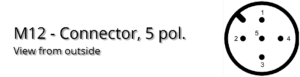
Pin assignment at the sensor with CAN, CANopen or SAE J1939
The pin assignment meets the specifications of the standards.
 |
||
| Pin | Color in the standardized CAN cable | CAN
CANopen SAE J1939 |
| 1 | Shield | CAN_Shield |
| 2 | Red | CAN_V+ |
| 3 | Black | CAN_GND |
| 4 | Weiß | CAN_H |
| 5 | Blau | CAN_L |
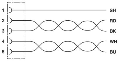 
We recommend the use of standardized CAN connection cables. |
||

Pin assignment at the sensor with current or voltage output
|
||
| Pin | Current
Voltage |
Notice |
| 1 | V+ | Supply Voltage +24V |
| 2 | B-Out | Sensor Output B (Standard Y) |
| 3 | V- | Supply Voltage Ground/ Sensor Ground |
| 4 | A-Out | Sensor Output A (Standard X) |
| 5 | Teach | Input for zero-point adjustment |
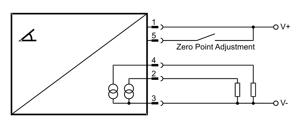 Connection diagram current output 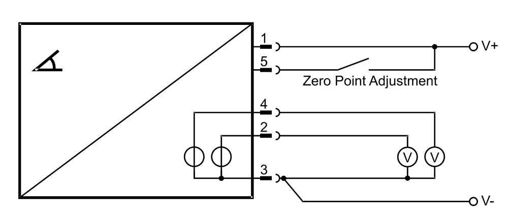 Connection diagram voltage sensor |
||
Pin assignment at the inclination switch
| Pin | 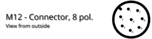 |
|
| 1 | A+ | Switching Output A + |
| 2 | A- | Switching Output A - |
| 3 | B+ | Switching Output B + |
| 4 | B- | Switching Output B - |
| 5 | T1 | Signal Programmer |
| 6 | T2 | Signal Programmer |
| 7 | GND | Ground |
| 8 | V+ | Supply Voltage |